Automatically water your plants with this 3d-printed system
After getting back from a 3-week trip my plants were not in a good mood, there was a heatwave when I was gone and not all plants survived. Time to think of a solution.
I had most of these parts laying around and it took suprisingly few parts to make this project work. There are probably better options for each part and an ESP8266 might be a bit overkill for what we’re doing here, but at less than 2 dollars I am not going to bother with other options.
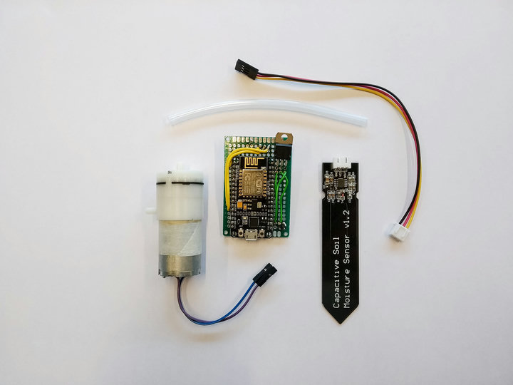
Above you can see the following parts:
ESP8266 NodeMCU (AliExpress). The brains of the operation, easy to use with the Arduino IDE and the surrounding print makes it easy to flash without having to solder certain pins and do other tricks.
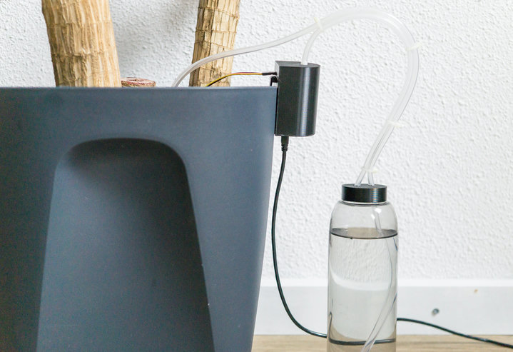
3v-5v Air pump (AliExpress). I chose an over-pressure system in favor of a water pump, as I wanted everything enclosed and I’d like to keep water as far away from electronics as possible.
Capacitive soil sensor (AliExpress). Most projects involving measuring soil water levels use a cheaper double-pronged circut board with metal. It corrodes quite fast, which this Capacitive soil sensor does not.
STP16NF06L MOSFET (AliExpress). The air pump works at 3volt, but not when connected directly to the NodeMCU digital out pin. Instead I hooked it up to the 5V VIN pin and use this mosfet with a digital out pin to trigger the air pump. There are probably better ways to do this, but it was the only thing I had laying around :).
4X6 cm Prototype Circut board (AliExpress). To solder the wires/Mosfet onto.
Some standard soldering stuff such as wires and male pins.
Total cost: € 10.00 or $ 11.00.
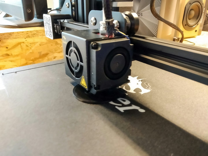
I didn’t want to have some electronics hanging around my plants so it’s time to put that 3d printer to good use. I fired up Fusion360 and came up with this design for an enclosure.
It just fits the pump and electronics and “only” takes about 4 hours to print.
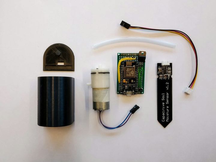
The soil sensor has to go into the plant pot and I’d like to hang the enclosure on the side of the plant pot. This means we need some way for the sensor to connect to the circut board inside the enclosure and ideally without having wires outside of the pot. With a bit of measuring I figured out a place to solder 3 male header pins on the bottom of the circut board and line up a hole in the enclosure. The hole also lets the air in for the pump to function.
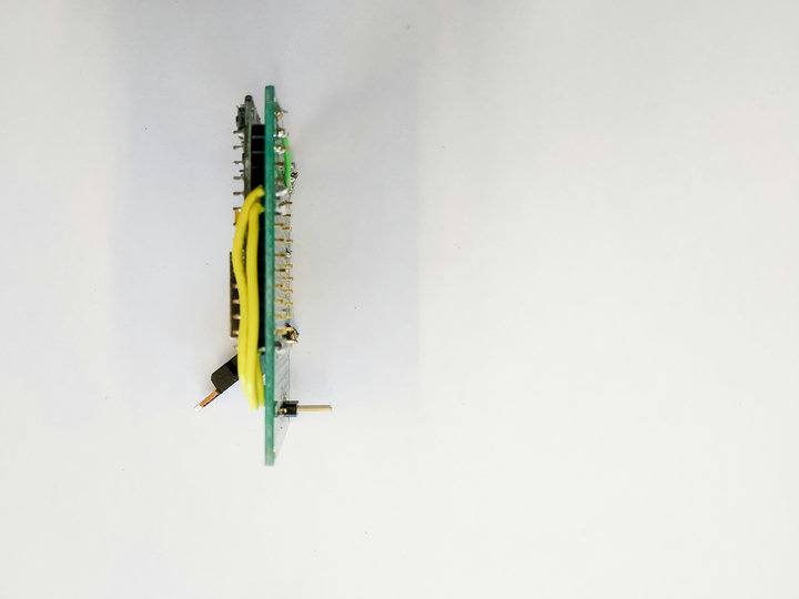
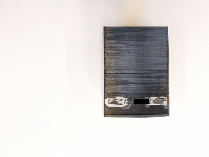
After glue-ing in the circut board and the motor we end up with a nice filled-out enclosure.
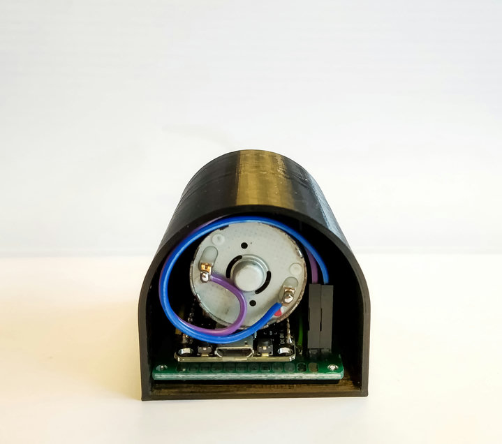
Time to load some code onto the NodeMCU.
Most of this build is based on the following instructables post: ESP8266 Soil Moisture Sensor With Arduino IDE. I modified the code to remove the webpage and altered the calculation for my version of the moisture sensor.
/* ESP8266 Moisture Sensor
   Original code from: https://github.com/dmainmon/ESP8266-Soil-Moisture-Sensor
*/
#include <ESP8266WiFi.h>

const char* ssid = "xxx";
const char* password = "xxx";
const int motorPin = 14; // ~D5
const int sensorPin = A0;

double analogValue = 0.0;
double analogVolts = 0.0;
bool runMotor = LOW;

void setup() {
  Serial.begin(115200);
  delay(10);

  pinMode(motorPin, OUTPUT);

  // Connect to WiFi network
  Serial.println();
  Serial.println();
  Serial.print("Connecting to ");
  Serial.println(ssid);

  WiFi.begin(ssid, password);
  // connect to WiFi router
  while (WiFi.status() != WL_CONNECTED) {
    delay(500);
    Serial.print(".");
  }

  Serial.println("");
  Serial.println("WiFi connected");
  Serial.println(WiFi.localIP());
  Serial.println("");
}


void loop() {
  analogValue = analogRead(sensorPin); // read the analog signal

  // convert the analog signal to voltage
  // the ESP2866 A0 reads between 0 and ~3 volts, producing a corresponding value
  // between 0 and 1024. The equation below will convert the value to a voltage value.

  analogVolts = (analogValue * 3.08) / 1024;

  // now get our chart value by converting the analog (0-1024) value to a value between 0 and 100.
  // the value of 400 was determined by using a dry moisture sensor (not in soil, just in air).
  // When dry, the moisture sensor value was approximately 400. This value might need adjustment
  // for fine tuning of the percentage.

  int percentage = ((analogValue * 100) / 850);

  // now reverse the value so that the value goes up as moisture increases
  // the raw value goes down with wetness, we want our chart to go up with wetness
  percentage = (100 - percentage) * 2;

  if (percentage <= 25) {  // 0-25 is "dry soil"
    runMotor = HIGH;
  } else {
    runMotor = LOW;
  }
  digitalWrite(motorPin, runMotor);

  // Serial data
  Serial.print("Analog raw: ");
  Serial.println(analogValue);
  Serial.print("Analog V: ");
  Serial.println(analogVolts);
  Serial.print("percentage: ");
  Serial.println(percentage);
  Serial.print("Run motor: ");
  Serial.println(runMotor);
  Serial.println(" ");
  delay(10000); // Sleep 10 seconds
}
The code does a few things, it connects to WiFi (not used rightnow, but will use it to send data to Home Assistant in the next iteration). Every 10 seconds it measures the soil mosture levels. If it’s below 25% it enables the motor, that will push air into the bottle and water out the other hose onto the soil.
Combine all the things together and you get this: a little device you can attach to your plant pot and a bottle of water with two hoses that will water your plant when the soil gets too dry.
